Car MP3 Player
Part 4 - Heat (Power) Supply
I don't claim to be any good at analogue electronic design. I'm not. This PCB was derived
largely from reference diagrams of the main ICs, and from other designs on the internet.
(I will find and post the references shortly).
I did however take RF interference into consideration, and laid out the PCB as efficiently
as I could. High-frequency tracks are kept as short as possible.
The 2-sided PCB has one side as a completely solid ground plane (except for
component leads of course). Also - zero wire links. That took some serious fiddling to
achieve!
Although I have no intention to market this design (it's only for me!), I did make it so that
it mounts directly into a standard ATX power supply case. This could be handy if I make
more of these in the future.
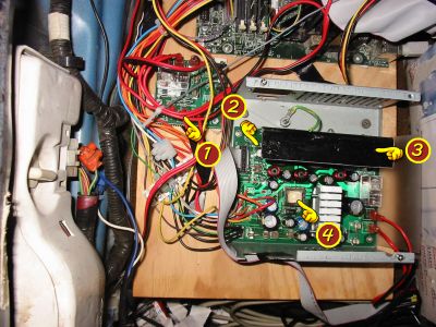
- UHS (Uninterruptable Heat Supply) controller. This ensures that even when the
car is turned off temporarily (up to 30 minutes), the heat supply can
continue to warm the boot and power the computer. This also ensures the
computer continues to run when the car is cranking (the rest of the car's electrical
system drops to 4-5 Volts and suffers large transient spikes).
Essentially just some diodes and a relay controlled by one of the micro-controllers
- Three buck-regulators. These three Maxim ICs can crank out 12 Amps on the 5-volt rail, and
up to 6 Amps on the 3.3volt rail. The two 5-volt ICs are bridged via a second pair of
LC filters, so that the feedback lines of the two ICs do not confuse each other.
- Sheet of Aluminium. Someone told me black transmits more heat than silver. It's co-incidence
anyway -- it was the first sheet of Aluminum I could find and bash into shape. Note,
The Heat Supply seems fine just using passive cooling - it's fairly efficient.
- Flyback regulator. This transformer magically gives +12V and -12V outputs -- even when the
input voltage drops to 9.5V, or raises to 16V. Amazing! I wish I'd thought of it!
Unfortunately, the +12V rail is very limited - it goes unstable if more than 1.4 Amps is
drawn or if the input voltage gets excessively low. However, this is sufficient for
the selected motherboard and hard-drive.
Hidden under the silver heat sink are also:
- A secondary 12V regulator (which can put out more current than the main +12V supply, but
its voltage will drop when the input voltage drops below 13V. It could be used for Fans and
less important hardware.
- A 5V-standby power source. This stays on even when the rest of the power supply is off
(required by the ATX specification). As this is a standard regulator, this actually puts
out the most heat of all the heat supply, even though it always stays under 300mA
The ICs I have chosen should all have built in current foldback or current limiting and
thermal overload protection. In theory, each output rail should be able to be shorted to ground
and/or each other, and the system will not fail and hopefully nothing will blow (except maybe the
main fuse if all the inputs are shorted to ground at once).
Do you think I've tested this though? Heck no!
I can't afford any more money than I've already spent on this!!!
Attaching the input battery in reverse polarity pops a fuse and destroys one diode.
I did *ahem* "test" this bit. (oops)