Car MP3 Player
Part 5 - The Microcontroller board
Yay! Digital Electronics. Now we're talking. This board is completely my own work, no
help from the internet and minimal use of reference diagrams.
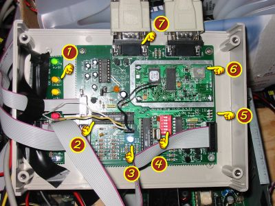
- Flashing Lights. Absolutely compulsory for any home project. Also very useful for
getting your microcontroller software to run before you have serial communications
implemented (or when compiler bugs stop your serial comms from working!)
LEDs will flash if the associated power rail is above or below ATX operating
specifications. The circuit is designed so that these lights can also be plugged
directly into the main Power Supply board, without any microcontrollers at all.
They will turn on when power is present, but will not flash.
- Microcontrollers. Microcontroller #1 is responsibile for measuring some of the
voltages of the power supply, and also monitoring the user-interface controls (the two
knobs and the volume potometer). This information is displayed on the LEDs and sent to
the Computer via a serial port. Microcontroller #2 is responsible for listening to
GPS positions, Infra Red input (when implemented), and measuring more voltages. It also
flashes LEDs, and sends data to the computer via microcontroller #1 (so that only
one Comm-Port is necessary at run-time)
Almost every feature of these versatile little puppys from Atmel
was used - timers, interrupts, A/D converters, high speed serial interconnect, UART interfaces,
in-system programming, flash memory, SEEPROM. They were programmed in C using the free
GCC compiler. (A welcome change from Assembler, but by no means as efficient).
- Blue LED A small investigation showed that a Blue Ultra-bright LED gave a more stable
reference voltage than a zener diode for the same about of current being drawn. Interesting.
Sounds like a perfect excuse to add more lights!!
- DIP switches One of the two microcontroller can be re-programmed in-system via
serial port 1, by adjusting these DIP switches.
- Infra-Red input never implemented, but I have implemented Infra-red sensors before.
It should not be hard to add.
- GPS. A Trimble Lassen-LP module to be precise. When operating normally, this sends
GPS positions using ASCII to microcontroller #2, which divides them into small packets and
sends them to microcontroller #1 which in turn sends them out the serial port. In the picture
however, the 2nd Serial port is connected directly to the GPS for debugging and GPS configuration.
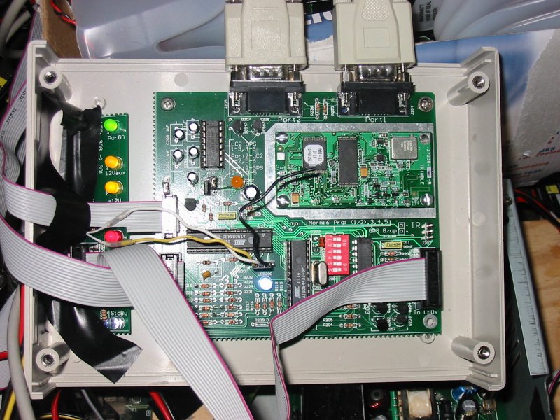
Now this is interesting. See how I left exposed metal on the PCB so that I could add sheilding
if required. I assumed that it would be. However, even with my unshielded switch-mode power
supply, a 530W amplifier, and great big sub-woofer all surrounding this poor little GPS unit...
It still picked up satellites quite happily. The signal from GPS satellites is smaller than the
background noise radiation from space! So this truely amazed me. It was also a big suprise, then,
to discover that the small spike from the car's brake-lights turning on caused it to loose track of
satellites! Drat!
I broke the antenna connection off shortly after my trip to Nelson. So I must fix that :-(
- Serial Ports. Enough said.
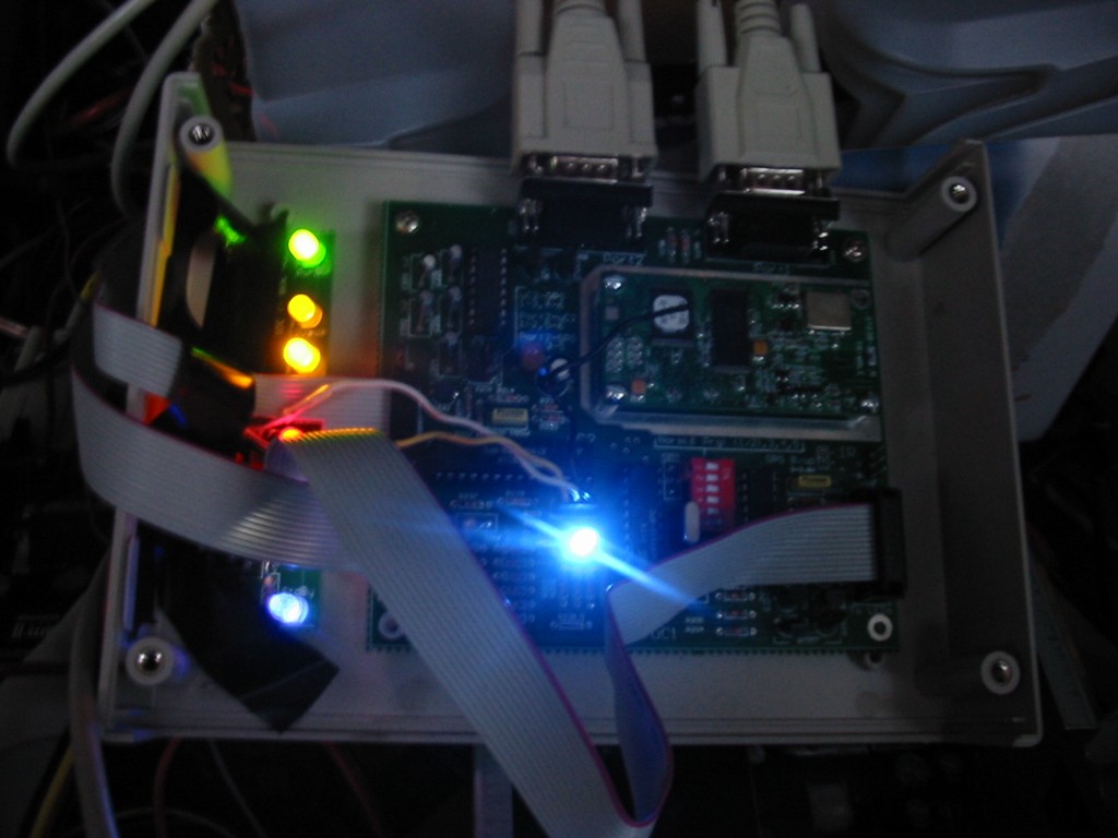
Ahh, doesn't it look pretty at night...
